Simply install it in the airflow path!
- High-precision digital air velocity output
- Easy detection of changes in airflow (air velocity)
Compact, Low-cost Digital Output Air Velocity Sensor: MMS651 Series

Are you struggling with measuring air velocity or detecting changes in airflow?
・Do you want to achieve highly accurate air velocity measurement, but the cost is too high?
・Do you want to easily detect changes in airflow at a specific location without connecting piping?
・Limited measurement space restricts where sensors can be installed.
・Resources are being spent on calibration and peripheral circuit design, delaying your development schedule.
The MinebeaMitsumi MMS651 Series solves all these problems!
MinebeaMitsumi’s MMS651 Series flow sensors are single-axis airflow sensors (air velocity sensors) that utilize the Seebeck effect* to convert a temperature difference into voltage. Equipped with MEMS technology and a 16-bit ΔΣ ADC, it minimizes electrical noise (interference) to the greatest extent possible, delivering high-precision digital air velocity output. The compact design and integrated connector eliminate installation constraints, providing a low-cost, high-performance solution ideal for heating, ventilation, and air conditioning (HVAC) and filter-clogging detection in servers and other equipment.
*Seebeck effect: A phenomenon in which a potential difference is generated when two different metal wires are connected at both ends to form a loop and a temperature difference is applied at the junctions.
1. Three Features That Solve Your Problems

- ① Resistant to electrical noise: Built-in 16-bit ΔΣ ADC provides high-precision digital output (I2C).
- ② Flexible installation: Compact design with a connector-equipped structure. Size: 22.5 × 21.0 × 7.0 mm!
- ③ No calibration required: Corrected digital values can be converted to air velocity values using a simple formula. This significantly reduces the resources required for peripheral circuit design and development time.
2. What Is the Secret behind the Internal Structure of the MMS651 That Enables it to Continuously Measure Air Velocity with High Accuracy?
The unique two-flow-path structure, which divides the interior into a main path and a sub flow path, reduces the amount of dust and dirt reaching the MEMS, enabling stable measurement over the long term.
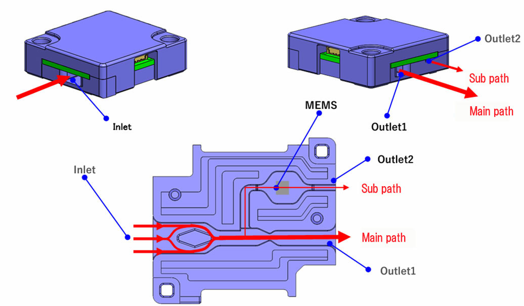
Inside the MMS651, air entering through the Inlet flows through the main path and is discharged through Outlet 1 and Outlet 2.
The key feature is the internal structure designed so that the airflow rate in the sub path is lower than that in the main path. This meticulous flow-path design physically suppresses the entry of dust and dirt into the sub path, where the MEMS chip essential for measuring air velocity is located. This helps prevent sensor deterioration and measurement errors caused by airborne dust, maintaining high measurement accuracy over the long term.
3. Specifications and Conditions
MMS651 Series Flow Sensor (Air Velocity Sensor) for highly accurate air velocity measurement in a compact, space-saving design with high resistance to environmental noise
Main Specifications
スクロールできます
|
MMS651P01N1 |
MMS651P003N1 |
|
|---|---|---|
| Applicable medium | Air | |
| Measurement range | 0~10 m/s (*) | 0~3 m/s |
| Accuracy | ±5%R.D. (4.0 m/s ≦ air velocity ≦ 10 m/s) ±2%F.S. (0 m/s ≦ air velocity < 4.0 m/s) |
±3%F.S. (0.3 m/s ≦ air velocity ≦ 3.0 m/s) ±7%F.S. (0 m/s ≦ air velocity < 0.3 m/s) |
| Supply voltage range | 3.0~3.6 VDC | |
| Operating temperature range | -10 ℃ to 60 ℃ | |
| Resolution | 16bit digital | |
| Response speed | 90msec. | |
| Interface | I2C | |
| Size (mm) | 22.5 x 21 x 7 | |
4. Application Examples for Addressing Challenges: Benefits of Using Airflow Sensors (Air Velocity Sensors)
Airflow sensors (air velocity sensors) are actively used in many aspects of our everyday lives, often behind the scenes.
For example, they can be used in ventilation fans and VAV HVAC systems, as well as for detecting filter clogging in data center servers, projectors, and other equipment.
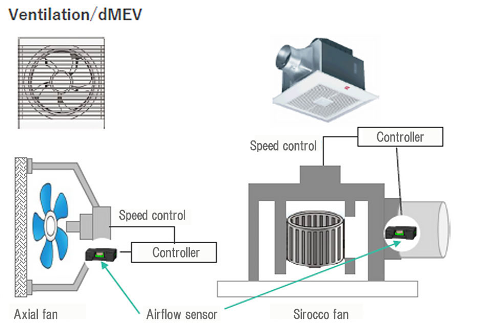
1) Ventilation fans / VAV (variable air volume control): Compliance with regulations (Ecodesign) and energy savings
Challenge
In response to recent Ecodesign-related regulations, there is a need to ensure the minimum effective ventilation volume while achieving energy savings.
Benefits
Installing the MMS651 in the ventilation path makes it possible to provide real-time feedback of the actual airflow to the controller. This enables optimization of exhaust efficiency and appropriate airflow control, contributing to energy savings and reduced noise.
2) Filter clogging detection (data centers / projectors): Optimizing maintenance
Challenge
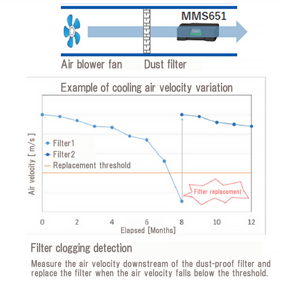
In the past, filter clogging was estimated based on elapsed time, such as the time the equipment had been powered on. This created the risk of unnecessarily replacing filters that were still usable, while also creating the risk of thermal runaway if replacement was delayed too long.
Benefits
The degree of clogging can be quantified by directly measuring the air velocity downstream of the dust-proof filter. This makes it possible to replace the filter at the optimal time when the air velocity falls below the preset threshold, helping ensure equipment safety while reducing component costs.