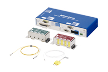
Molding pressure conversion module MPC-201B-25
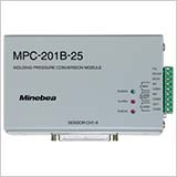
A specialized digital conversion module of 8-channels inputs that measures the mold cavity pressure of the injection molding machine.The pressure value is watched on the condition set beforehand, and the result is output as an alarm signal. Forward the pressure value waveform converted into the analog voltage to the molding machine.
【Features】
・The mold cavity pressure can be measured, managed and recorded easily with low cost. Up to now, that was a Black Box though the pressure was an important parameter in a quality of molded products.
・The actual measuring waveform of the pressure when the resin is filled into the forming die is useful to manage the quality of molded product.
・Shorten the time for optimizing the molding condition by an experimental trial and for matching the condition in mass production factory.
・The product quality in mass production can be determined by setting the condition of the determination based on the pressure waveform of non-defective product.
Features
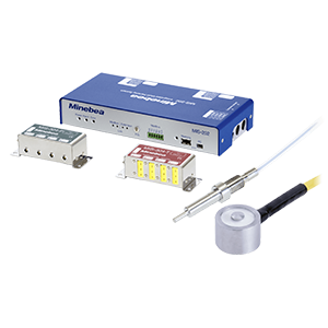
・A special conversion module of 8-channels input that measures the mold cavity pressure of the injection molding machine.
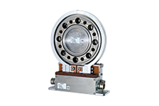
・Attach the relay box MPC-308 that is convenient for wiring between the amplifier and the sensor built into the metal mold of the injection molding machine.
・The pressure value is watched on the condition set beforehand, and the result is output as an alarm signal.
・Forward the pressure value waveform converted into the analog voltage to the molding machine.
・The real time waveform of the pressure value is displayed, stored, read out, analyzed, and set variously by using the attached application software of a personal computer.
・CE mark applied product.
-
-
scroll
Specification name
Specification contents
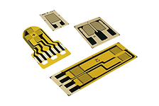
< Analog input > Bridge power supply 5 VDC±0.25 VDC within 20 mA (per one channel) Applicable sensor LSMSB-5K~3T/LSMS-20K~3T-S06
(350 Ω, 1 unit/channel)Numbers of input points Up to 8 points Input range -0.1 mV/V ~ 0.8 mV/V Zero adjustment range Adjustable between -0.1 mV/V ~ 0.7 mV/V using zero set function Accuracy ±2.0 %F.S. Sampling interval 10 ms for each channel
(Changeable to 0.5 ms, 1 ms, 2 ms, 5 ms, 20 ms or 50 ms.)A/D internal resolution 16 bit Analog filter Approx. 500 Hz < Analog output > Numbers of outputs 8 points Output voltage 0 VDC ~ 10 VDC Load resistance 5 kΩ or less Resolution 1/12 000 or more Output frequency Synchronized with A/D sampling rate. Over range Approx. 11 V at 110 % or more of the rated pressure.
Approx. -1 V at -10% or less of the rated pressure< Digital specifications > Measurement range 0 MPa ~ 999.99 MPa (Conversion value from pressure receiving area) Status LED POWER, ALARM, ERROR < Various functions > Set of measurement condition Set of sensor, Set of measuring time, Input signal set of START,
Delay time set of START and Protruding detection time setALARM function set Effective/Invalid set of channel, ALARM output signal set,
Watch frame condition set (Area watch, Watch at the peak, Watch at (t) second later, Set of integral value condition (Watch integral value, Watch at the peak arrival timeSet of alarm reset ALARM RESET time set, ALARM RESET signal set USB interface Conformed to USB Specification 2.0/1.1, Mini$USB B$type connector (Female)
* Installation of the attached special driver software for PC is required.Special application software for PC MIP-D-02
Waveform display function Sequential waveforms, Overlay waveform), Measurement processing function, Peak pressure display,
Integral value display, Counter of shot number, Measurement condition setting function, Set of analog voltage output, Data storing function, ALARM judgement function, Data Processing function, Check function, Statistical process function, Screen printing capability, Password function< General Specifications > Operating temp./
humidity rangeTemperature -10 ℃~50 ℃
Humidity 85 %RH or less (Non Condensing)Stored temperature range -20 ℃ ~ 60 ℃ Vibration resistance 10 ~ 55 Hz double amplitude 1.5 mm, 2 hours for each direction of X, Y or Z. Power supply Power supply voltage: DC24 V (Available variable range DC20.4 V ~ DC27.6 V), Power consumption: Approx. 6.5 W (at DC24 V) Outline dimensions 160 mm × 98 mm × 40 mm (Excludes protruding parts.) Weight Approx. 800 g Installation mount on the metal surface with the magnet. Accessories USB cable 2.0 m, Ferrite core, Plug for power supply and external control I/O, Plug for analog voltage output, CD-ROM, Instruction manual -
Instruction Manual
Specification sheet
CAD files[DXF]
Software
-
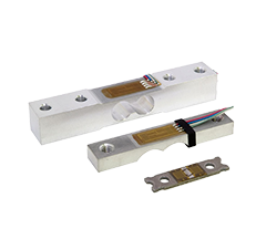
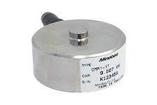
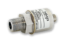
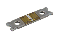
- Load cell LSMSB-*/LSMS-*-S06
- External control I/O cable 2.5 m (FA409-477)
- Analog voltage output cable 2.5 m (FA409-476)
Custom

- ※Custom products are intended for mass production. Please consult us for small-lot orders.
Featured Products
Case Studies

Download
Product Topics
Industry


Contact Us
Please click the inquiry type below according to your question. Each product / sales representative will respond to you.