Drive circuit and wiring diagram
Product Catalog
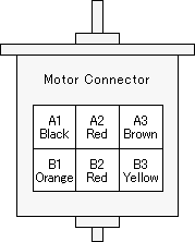
Show the drive circuitry and stndard color of lead wire.
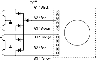
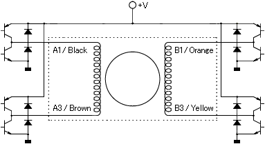
1) Drive Circuitry
( UNI-POLAR DRIVE )
( BI-POLAR DRIVE )
2) Switching Sequence << Using the Drive Circuit Indicated Above >>
( UNI-POLAR DRIVE )
スクロールできます
|
A1 |
A3 |
B1 |
B3 |
A2/B2 |
|
|---|---|---|---|---|---|
| 1 | - | - | + | ||
| 2 | - | - | + | ||
| 3 | - | - | + | ||
| 4 | - | - | + |
( BI-POLAR DRIVE )
スクロールできます
|
A1 |
A3 |
B1 |
B3 |
|
|---|---|---|---|---|
| 1 | - | + | + | - |
| 2 | - | + | - | + |
| 3 | + | - | - | + |
| 4 | + | - | + | - |
The rotation direction is as viewed from the front end.
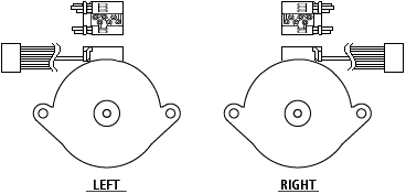
3) Wiring Diagram << WIRE HOLDER Method >>
( STANDARD W/H DIRECTION )
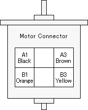
( Standard Wiring Color )
スクロールできます
|
MOTOR |
WIRE COLOR |
MOTOR |
WIRE COLOR |
|---|---|---|---|
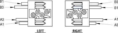
| A1 | Black | B1 | Orange |
| A2 | Red | B2 | Red |
| A3 | Brown | B3 | Yellow |
( PM15S )
( PM20, PM25 )
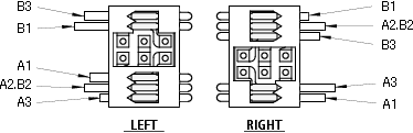
( PM35, PM42, PM55 )
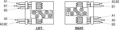
( PM42M )
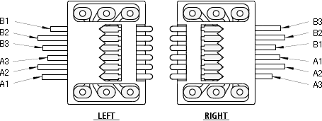
4) Motor Unit Wiring Diagram << IDC Method - Standard Wiring Color >>
( UNI-POLAR DRIVE )
( BI-POLAR DRIVE )
Related page
Engineering Information for PM stepping motors
Technical Data
Precautions of Use
Explanation of Technical Terms
Contact Us
Please click the inquiry type below according to your question. Each product / sales representative will respond to you.