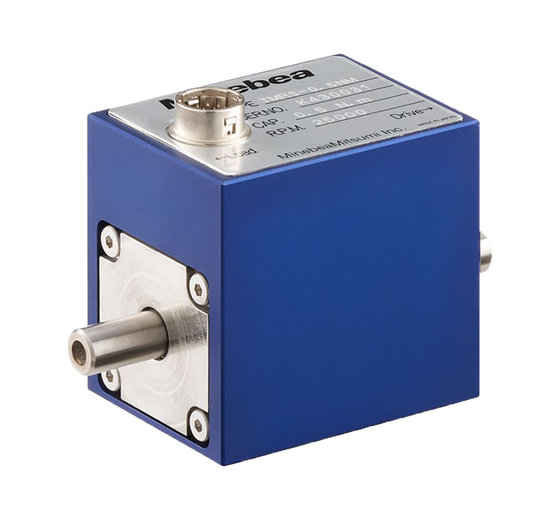
Appearance

■Strain gage type Optical transmission method torque transmitter
■High zero stability and reduced rotational zero movement
■Compact and lightweight design
■Ultimate overload 500%F.S.
■High Responsive 6kHz
■A/Z function performs zero point correction
Specification
| Specification name | Specification contents |
|---|---|
| <load characteristics> | |
| Rated capacity | ±0.5N・m、±1N・m、±2N・m |
| Safe overload | 500 %R.C. |
| Measurement accuracy | ±0.03 %R.O.(Linearity, hysteresis and repeatablity are included) |
| <input characteristic> | |
| Power supply | DC24V±15% |
| Power consumpson | 0.2A or less |
| Torque output | ±10 V voltage output, load resistance 2 KΩ min |
| Torque output measurement frequency range | 6 kHz |
| rotational pulse output | 4-pulse output per revolution rotaion,open collector output,Rated DC30V 10mA |
| <Temperature characteristics> | |
| Temp. range, safe | -20 ℃ to 60 ℃ |
| Note for temperature range | -10 ℃ to 50 (non-condensing) |
| Temp. effect on zero balance | 0.1 %R.O./10 ℃ |
| Temp. effect on output | 0.1 %LOAD/10 ℃ |
| rotational characteristic | |
| Max. rpm | 25 000 rpm |
| <other> | |
| Material | Sensor shaft: stainless steel; bearing housing: stainless steel; housing: aluminium alloy |
| Durability | 10,000,000 times with rated load applied |
| Gross weight | Approx.240 |
| Class of protection | IP40 |
| <Mechanical characteristics(rotor)> | |
| Inertia moment | 0.5 N・m:1.46 kg・mm²、1.0 N・m:1.48 kg・mm²、2.0 N・m:1.52 kg・mm² |
| Torsional rigidity | 0.5 N・m:236 N・m/rad、1.0 N・m:318 N・m/rad、2.0 N・m:531 N・m/rad |
| Torsional peculiar pitch | 0.5 N・m:5.01 kHz、1.0 N・m:5.67 kHz、2.0 N・m:6.61 kHz |
Table of P/N
| Parts No. | Rated capacity [N・m] |
Maximum rotation speed [rpm] |
Mechanical characteristics Inertia moment [kg・cm²] |
Mechanical characteristics Torsional rigidity [N・m/rad] |
Mechanical characteristics Torsional peculiar pitch [KHz] |
Accurate allowable bending load [N] |
Accurate allowable thrust load [N] |
Cable | 3D CAD files [STEP] | Weight(Approx.) [g] |
|---|
・Accurate permissible bending and thrust loads are those loads (measured values) with an output error of 0.05% R.O.
・Accurate permissible bending loads are the result of fixing the enclosure and applying the load on the axis of rotation 33 mm from the enclosure end face.
・All values are guaranteed for static loads.
Download
Instruction Manual
Specification
Options
- Exclusive signal cable Model:RC041-*M(selectable from 2m、5m、10m)
