3 Piece Rod End Bearing
3 Piece Rod End Bearing
The load ratings of Rodend bearing shall be determined by the strength of body, because of it is a critical component compared to the inserted Spherical bearing.
Definition of Load
- Static Limit Load
- Static limit load is the load, which does not disturb the Rod End performance. It is calculated with the yield strength.
- Static Ultimate Load
- Static ultimate load is the radial tensile static load, which can be applied without distracting Rod Ends.
- Axial Proof Load
- This is the load, which does not push out spherical bearing when applied statically from axial direction.
- Fatigue Load
- The load which is bearable for 50,000 cycles with 100~10 % of continuous tensile load.
Calculation of load capacity
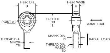
When static load is applied, most Rod Ends fail at point A (Figure 10). Under ordinary situations, shank has more strength than point A, however, both the strength at A (B.S.A) and at shank (S.S.A) shall be discussed.


- Rod End body head minimum cross section
- Cross section at Point A in Figure 10 is calculated as follows;
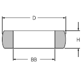
 Or approximately: B.S.A. = (D - BB) × H (Figure 11)
 - Shank cross section
- Male Rod End S.S.A. :

Female Rod End S.S.A. :
- Allowable stress
- Minebea uses the allowable stress values given in the table. The allowable values are based on the actual test results. Minebea use figures in Table 10, which are the results of several examinations
|
Body Material |
Ultimate Static Load |
Static Limit Load |
Fatigue Load |
|---|---|---|---|
| 4340 39-42HRC |
1171N/mm2 { 119.5kgf/mm2 } |
937N/mm2 { 95.6kgf/mm2 } |
372N/mm2 { 38.0kgf/mm2 } |
| 4130 36-42HRC |
1068N/mm2 { 109.0kgf/mm2 } |
855N/mm2 { 87.2kgf/mm2 } |
309N/mm2 { 31.6kgf/mm2 } |
| SUS630(17-4PH) 36-42HRC |
1068N/mm2 { 109.0kgf/mm2 } |
855N/mm2 { 87.2kgf/mm2 } |
345N/mm2 { 35.2kgf/mm2 } |
| SCM435H 35-40HRC |
1034N/mm2 { 105.5kgf/mm2 } |
827N/mm2 { 84.4kgf/mm2 } |
172N/mm2 ※ { 17.6kgf/mm2 } |
-
*Fatigue strength could be improved up to 275N/mm2{ 28.1kgf/mm2 } by applying extra surface finishing between the head and the shank. They are considered as special items.
- Rod End body fatigue failure
- In the same way as distraction occurs under static load, fatigue failure is seen at point A (Figure 10). Depending on the bearing design, however, it may happen at shank or in tangential area between head and shank. Machining ridges and scratches could cause high-tension stress, by which fatigue is remarkably influenced. They can cause cracks and eventually develop to fatigue stress. When fatigue strength is discussed, the bearable cycle calculation may be necessary under a given load. In addition, fatigue is easily influenced by stress wave, stress concentration, and environmental condition. Please consult with our Sales to estimate the fatigue life, as it is a very complex matter without reliable testing results.
- 3 Piece Rod End axial load capacity
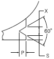
- The staking strength determines the axial load capacity of 3 Piece Rod End. The axial proof load of V-staked Rod End can be estimated from Table 11. The actual load which pushes the spherical out of the body is at least 1.5 times higher than axial proof load. When oscillation or shock applies, it may, however, start pushing the spherical out even with lower load than axial proof load. Therefore when dynamic load applies, 1/3 of axial proof load is the recommended maximum load. Axial proof load of body staked Rod Ends is equivalent to V-groove types.
|
V-Groove |
|
|
|
Axial Proof Load (N) { kgf } |
|
|---|---|---|---|---|---|
| Steel Race (30 ~ 35HRC) | Al-Bz Race | ||||
| A | 1 | 0.7 | 0.5 | 298 × D { 30.4 × D } | 193 × D { 19.7 × D } |
| B | 1.4 | 1 | 0.7 | 367 × D { 37.5 × D } | 239 × D { 24.4 × D } |
| C | 2 | 1.5 | 0.7 | 411 × D { 42 × D } | 267 × D { 27.3 × D } |
-
D = spherical bearing outer diameter (mm)

Related page
Engineering Information for Rod End Bearings
Technical Data
Contact Us
Please click the inquiry type below according to your question. Each product / sales representative will respond to you.