When an external load is applied to the rolling ball bearing, deformation (displacement) occurs at the contact points between balls and raceways.
Radial displacement

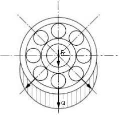
As shown in Figure 13-1, when the radial load (Fr) is applied, the maximum load (Q) applied to the
ball is

Z:
Number of balls
Radial displacement (δ) at the contact points between balls and raceways is

 : Coefficient determined by relationship between balls and raceways
Σρ : Sum of principal curvatures of contact points
Since the ball is in contact with the inner and outer rings, the total displacement will be the sum of the displacements of both.
δr : Total radial displacement
δi : Radial displacement between balls and inner ring raceway
δe : Radial displacement between balls and outer ring raceway
otal displacement (δr) is represented as follows.
δr = δi + δe
Axial displacement
the axial displacement (δa) when the axial load (Fa) is applied by the following method.

c: Contact
elastic modulus
Relationship between initial contact angle (α0) and contact angle (α)

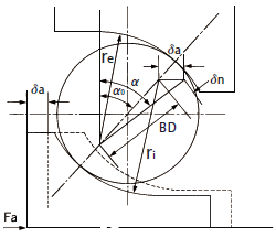
When moving one of the raceway rings in the axial direction until clearance disappears, the initial contact angle shown in Figure 13-2 (α0) is obtained as follows.

Gr : Radial clearance
ri : Inner ring groove curvature radius
re : Outer ring groove curvature radius
Dw : Ball diameter
As shown in Figure 13-2, the relational expression between the contact angle (α) and initial contact angle (α0) generated when a load (Fa) is applied in the axial direction from the initial contact state is as follows.

Related page
Engineering Information for Miniature & small ball bearings
Selecting the Right Part
Technical Data
Contact Us
Please click the inquiry type below according to your question. Each product / sales representative will respond to you.