What is a shunt regulator?
1. What is a shunt regulator?
A shunt regulator is a type of a linear regulator to keep voltage constant.
Linear regulators are largely classified into "shunt regulators" and "series regulators."
Both of them can generate a stable voltage lower than the input voltage from an unstable input voltage.
Shunt regulators generate a stable voltage by drawing current through a resistor for voltage drop.
They are mainly used as reference voltage and often used in equipment for daily use such as AC-DC switching power supply circuit.
2. Difference between a shunt regulator and a series regulator
Circuit configuration is different
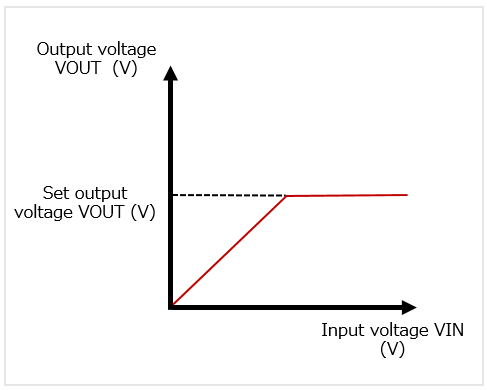
In both shunt regulators and series regulators, the output voltage is kept constant at a set value after the input voltage is increased.
Both series regulators and shunt regulators are types of linear regulators.
As in Figure 1, as the input voltage of a regulator is increased, the output voltage rises linearly until it is fixed voltage, and is constantly controlled when it reaches a certain level.
Shunt regulators have control elements in parallel with the load while series regulators in series with the load.
* Capacitors and other components have been omitted for simple description.
Shunt regulators and series regulators, both of which are used to control the effect of output voltage caused by the fluctuation of input voltage and supply reliable power, configure a circuit differently.
Configuration of a shunt regulator
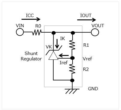
* In MM1431 series, a cathode current (IK) of 0.6 mA to 50 mA is recommended.
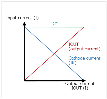
In a regulator using shunt regulator (Figure 2 Configuration example A), the voltage is constantly controlled by drawing a cathode current (IK) through a resistor connected to the input stage and producing voltage drop. Therefore, it tends to consume a large amount of power because it receives the same current (IIN) as the one at a maximum load even when the output current is small (refer to Figure 2/ Figure 3). The great advantage of shunt regulators is to generate high-precision reference voltage (Vref) easily, which is why they are used in various electronic circuits.
Configuration of a series regulator
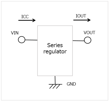
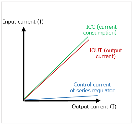
On the other hand, series regulators have control elements in series with the load (Figure 4 Configuration example B). Compared with a series regulator configured with a shunt regulator, the current consumed in the control circuit is almost the same as the output current. This results in few power losses at no load, and enables efficient voltage stabilization (refer to Figure 4 / Figure 5).
3. What shunt regulators can do (examples of application circuits)
Circuit configuration using a shunt regulator is used in various electric circuits. This section shows examples of application circuits configured with a shunt regulator.
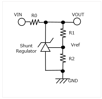
[1] Configure a reference circuit (Figure 6)
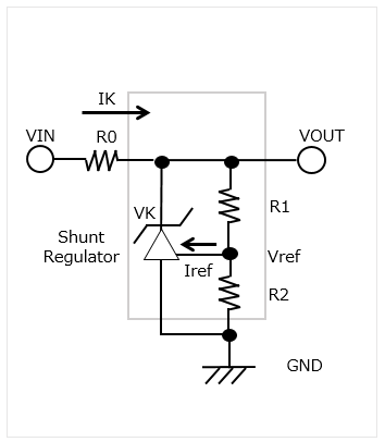
The most basic reference circuit using a shunt regulator can be shown in the following equation:
VOUT = Vref * (R1 + R2) / R2
A shunt regulator enables to configure a reference voltage source with a few elements.
* It must be configured while considering VOUT, which changes with the effect of VK and IK.
[2] Configure a series regulator (Figure 7)
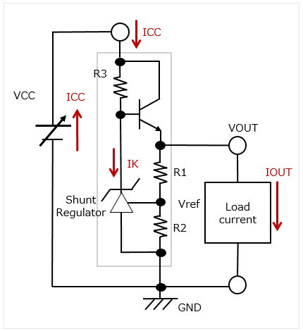
This is an example of a series regulator circuit using a shunt regulator. Such a circuit allows for a simple series regulator to be easily configured with a few discrete elements.
It outputs a certain level of voltage without being affected by IOUT, as in the shunt regulator alone. It can also output a current larger than the shunt regulator's maximum cathode current by driving a power transistor at the output stage.
The circuit can be shown in the following equation:
VOUT = (1 + R1 / R2) Vref
[3] Configure a constant-current source (Figure 8)
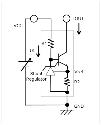
This is an example of a circuit configuration used when the constant current is required. It can be shown in the following equation:
IOUT = Vref / R2
This is useful in driving with a constant current because the circuit can drive IOUT stably.
[4] Configure the reference power supply of control voltage at the secondary side of AC-DC switching power supply (Figure 9)
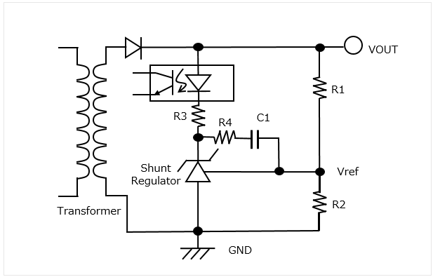
This is an example of a driving circuit of an AC-DC converter using a photocoupler. The output voltage at the secondary side can be shown in the following equation:
VOUT = Vref * (R1 + R2) / R2
The current flowing in the photocoupler is sent back to the primary side and controls VOUT.
The photocouplers R4 and C1 are used to prevent oscillation in a snubber circuit.
4. Shunt regulator's main characteristics
The following explains the main characteristics of shunt regulators based on the example of MM1431 series.
-
[1]Reference voltage characteristics
-
[2]Load regulation
-
[3]Reference input current
VOUT=(1+R1/R2)Vref
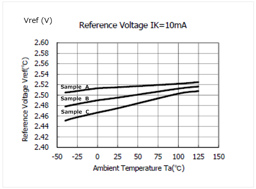
* The reference voltage characteristics of MM1431 series include increasing temperature. This must be considered when setting the output voltage.
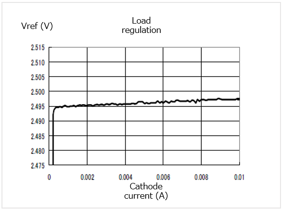
* The minimum cathode current is equivalent to current consumption. In MM1431 series, 0.3 mA or more is recommended to maintain stable operation.
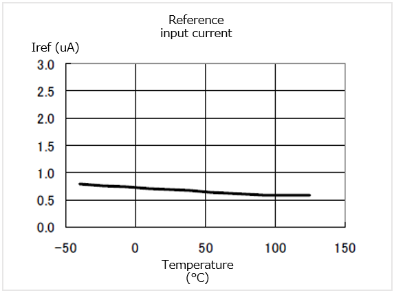
* This is the characteristics of temperature of input current flowing to the reference terminal.The specification defines "1uA Typ. (Ta = 25°C)."
5. How to choose a shunt regulator
The shunt regulators of MinebeaMitsumi have two types of reference voltage (1.25 V and 2.50 V).
The lineup is classified by various categories such as precision, absolute maximum rating and package.
6. Shunt regulators of MinebeaMitsumi
Shunt Regulator (reference voltage: 2.495 V)
Item |
Reference voltage Typ. (V) |
Reference voltage accuracy Typ. |
Absolute maximum ratings (V) |
Recommended operating conditions |
Operating temperature |
Package |
Pin configuration |
|---|---|---|---|---|---|---|---|
| MM1431CU | 2.495 | 0.8% (±20mV) | 35 | 0.6mA~50mA | -30℃~+105℃ | SC-82ABB | 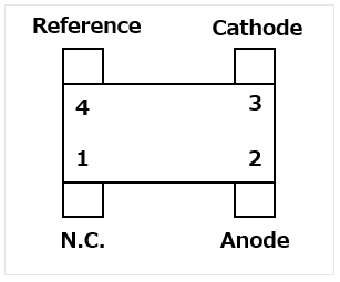 |
| MM1431DU | 2.495 | 0.4% (±10mV) | 35 | 0.6mA~50mA | -30℃~+105℃ | SC-82ABB | |
| MM1431CN | 2.495 | 0.8% (±20mV) | 35 | 0.6mA~50mA | -30℃~+105℃ | SOT-25A |  |
| MM1431DN | 2.495 | 0.4% (±10mV) | 35 | 0.6mA~50mA | -30℃~+105℃ | SOT-23A | 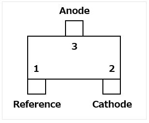 |
| MM1431EN | 2.495 | 0.8% (±20mV) | 35 | 0.6mA~50mA | -30℃~+105℃ | SOT-23A | 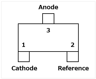 |
| MM1431FN | 2.495 | 0.5% (±12mV) | 35 | 0.6mA~50mA | -30℃~+105℃ | SOT-23A | |
| MM1431GN | 2.495 | 0.8% (±20mV) | 35 | 0.6mA~50mA | -30℃~+105℃ | SOT-23A | |
Shunt Regulator (reference voltage: 1.24V-1.27V)
Item |
Reference voltage Typ. (V) |
Reference voltage accuracy Typ. |
Absolute maximum ratings (V) |
Recommended operating conditions |
Operating temperature |
Package |
Pin configuration |
|---|---|---|---|---|---|---|---|
| MM1530CU | 1.270 | 0.8% (±10mV) | 12 | 0.3mA~15mA | -30℃~+105℃ | SC-82ABB | |
| MM1530DU | 1.250 | 0.8% (±10mV) | 12 | 0.3mA~30mA | -30℃~+105℃ | SC-82ABB | |
| MM1530DN | 1.240 | 0.5% (±6mV) | 12 | 0.3mA~30mA | -30℃~+105℃ | SOT-23A | |
| MM1530EN | 1.270 | 0.8% (±10mV) | 12 | 0.3mA~15mA | -30℃~+105℃ | SOT-23A | |
| MM1530JN | 1.240 | 0.5% (±6mV) | 12 | 0.08mA~15mA | -30℃~+105℃ | SOT-23A | |
If you need products in small lots, please check the following links.

For product-related inquiries, please contact us using the form below.
Related page
Contact Us
Please click the inquiry type below according to your question. Each product / sales representative will respond to you.