Outline of 70DCF
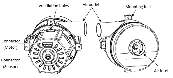
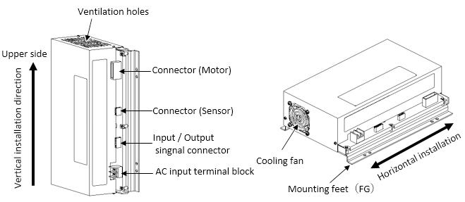
Part names
Blower
Driver
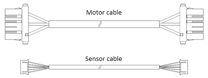
Wire
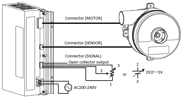
Connection Diagram
| Terminal Block | No.1 | ACL | Connector (SIGNAL) | No.1 | DC_OUT |
|---|---|---|---|---|---|
| No.2 | ACN | No.2 | S_CTR | ||
| chasis | FG | No.3 | CTR_GND | ||
| No.4 | FOLT | ||||
| No.5 | FOLT_GND | ||||
| Connector (MOTOR) | Motor Connector Input of Blower |
No.6 | PULSE | ||
| Connector (SENSOR) | Sensor Connector Input of Blower |
No.7 | PULSE_GND | ||
- If terminal block is placed near the Blower,make sure vibration/air stream does not cause mechanical fatigue of wire. Fixed attachment to a nylon clamp and / or duct is recommended.
- Driver connection to an AC power supply input terminal block should be firmly fixed using a crimp-type terminal with an insulating cover(ex. V2-P4 JST) and electric wire equivalent to or larger than 2mm2.
- Make sure connector is pushed all the way down.
Rotation Speed Modulator
- The Blower output can be adjusted by adjusting The input voltage between The control I/O connector terminal S_CTR and The CTR_GND terminal.
- Conventionally, the external power supply was required for the Blower output, we provide with a reference voltage output for the output variable.So,the blower output can be adjusted by connecting a variable resistor to DC_OUT and S_CTR and CTR_GND.
Input voltage : 0VDC to 5VDC, Input current : 1mA or less - Please input the DC voltage that meets the input voltage specification between the terminal S_CTR and the terminal CTR_GND.
AC Power Supply Voltage Range
|
Voltage |
Freqency |
|
|---|---|---|
| AC180V - AC264V | 50/60Hz | |
Connection hoses
If the blower is used without a hose connected for the intake port, a high pitch resonant sound may be generated.
If this happens, use a duct connection hose or the special opening.
Φ50 diameter hoses will fit.
Hoses manufactured by the Tiger Polymer Corporation, for example.
There are connection hoses by other manufacturers that will fit as well.
Consult with hose manufacturers regarding hose specifications that are best for your intended application and then select a hose.
The air temperature of discharge parts will increase under certain operating conditions and environments.
Therefore, we ask that you use a heat-resistant hose.
If the hose is used at high pressures, it may become disconnected so you must affix a band to it.
Connection
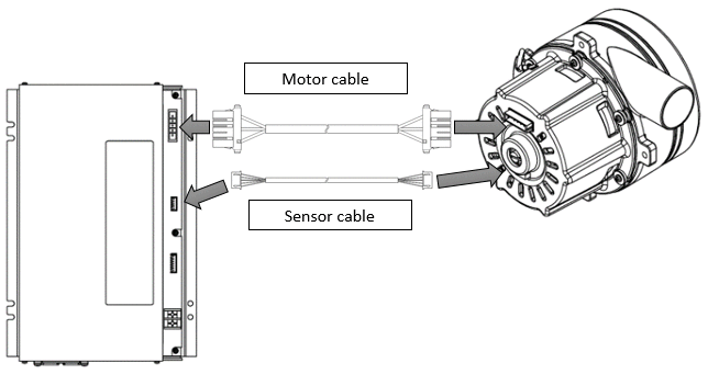
1. Connection of driver and blower
The blower and driver are connected by a special relay cable.
There are two types, one for the motor connection and one for sensor connection.
Plug the connector cable into the connector for the blower and driver.
|
Precautions |
Firmly insert the connector as far as it will go. If the connector is not in fully, the equipment may run improperly or the blower and driver could be damaged. |
|
Precautions |
When connecting or disconnecting the connector, always grab hold by the connector. Do not pull by the lead wire. Do not force in a direction other than the direction intended for insertion and removal. |
|
Precautions |
Do not try to modify the cable by cutting it to extend or shorten it. Do not try to connect directly to the terminal because it may make the equipment run improperly or the blower and driver could be damaged. |
Select a cable length that is best for the equipment you are using.
| Number of product | Cable length |
|---|---|
| 241-70-705-01 | 1m |
| 241-70-705-02 | 3m |
| 241-70-705-03 | 5m |
When using a long cable, make certain that it is not susceptible to the external noise of equipment.
(Detach the cable from the power line. Disconnect the sensor cable. Shield the cable.)
The connection of driver and blower must be done using a special cable.
When mounting the terminal block close to the blower, watch out for mechanical fatigue of the cables caused by shaking and wind.
We recommend that you affix nylon clamps and ducts.
Do not carry the blower and driver while they are in their cables.
2. Connection of Power
Input power connection example
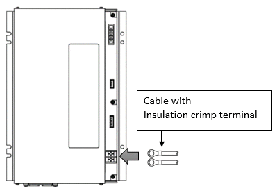
Power input: 200 VAC (single phase) 180 V to 264 V.
You must furnish the power cable.
The wiring for the lead wires to the AC input terminal block of the driver could short circuit if they contact the driver cover.
Therefore, use an insulated round crimped terminal.
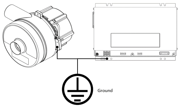
We recommend you use cable with a wire diameter of AWG16 (1.3 mm2) or higher Connect a ground wire to the cases for the driver and blower, or firmly ground the case.
After wiring is complete, be sure to place the terminal block cover back on before using the blower.
|
Precautions |
When connecting the power supply wiring avoid placing wiring within the same ductwork so as to prevent the influence of noise on other signal lines. Remove the power cable after confirming that the electric potential for the power supply terminal block has dropped enough. Use a wide, large, and uniform conductive surface as a ground location. ground so that no electric potential difference will be generated. Ground in such a way that all grounding points are on the shortest path to a single point. |
Ground example
3. Connection of input and output signal cable
Input and output signal cable connection example
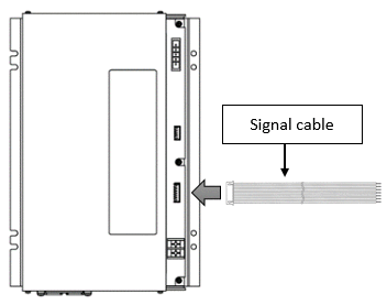
Plug the I/O signal connector into the connector part for the driver.
The color display on the diagram represents the color of the accessory cables.
If you do not use the connector provided with the blower, you must make a cable using the parts described in the provision below.
Do not connect directly and do not use items of another name nor items by other manufacturers.
| Name of parts | Number of product | Manufacturer |
|---|---|---|
| Housing | XHP-7 | JST |
| Terminal | SXH-001T-P0.6 | JST |
For details, please refer to the wiring example.
Related page
Engineering Information for High-pressure blowers
Technical Column
Technical Data
Precautions of Use
Contact Us
Please click the inquiry type below according to your question. Each product / sales representative will respond to you.