DC Fan Sensors
DC Fan Sensors
There are two types of DC fan sensors available: Locked Rotor Signal and Tachometer Signal. The lock Signal outputs the status of the fan motor and is designed to detect if the fan motor is rotating or stopped. The Tachometer Signal is designed to detect the fan speed. It is set to produce two cycles of rectangular waveforms as the fan motor makes one rotation.
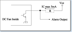
Output Circuit: Alarm Signal Circuit
Output Circuit: Open Collector
Specification
Vce max : +30V
Vce max : +15V
Ic max : 5mA(Vce(sat)max=0.4V)
TTL output is an available option.
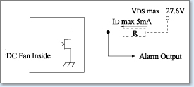
Output Circuit: Open Drain
Specification
VDS max : +27.6V
ID max : 5mA(Vo(LOW)max=0.5V)
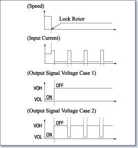
Lock Signal
This Fan Motor has Three Lead Wires
Output Signal: White, +:Red, -: Black
The output signal may correspond to Case 1 or Case 2.
* The output completely becomes at VOL in less than 0.5 sec. after switch-on.
Your design should provide for both waveforms.
Tachometer Signal
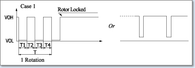
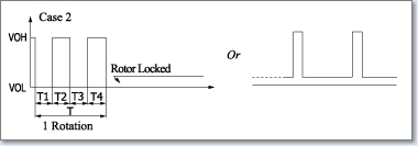
T=T1+T2+T3+T4=1 Rotation, T1≈T2≈T3≈T4 60/4m m: Rotation Speed min-1
The output signal may correspond to Case 1 or Case 2. Your design should provide for both waveforms.
Related page
Engineering Information for DC fan motors
Technical Data
Contact Us
Please click the inquiry type below according to your question. Each product / sales representative will respond to you.