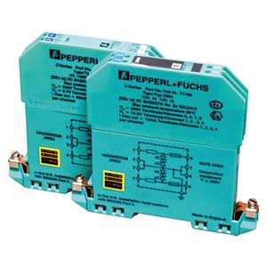
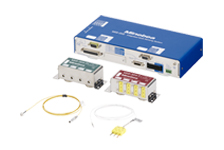
Zener barrier Z961-TC20162/Z964-TC20163 (after 2012)
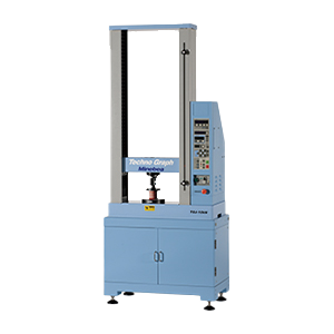
The devices compose a weighing system and those are used to connect the sensor with the equipment for instrumentation.
Features
Safety barrier for load cell to be used for intrinsic safety explosion proof weighing system.
Meets the intrinsic safety explosion proof requirement of Technology Institution of Industrial safety in Japan.
The type of Z951/Z964 to be applied is different in the model passed before 2011 and the model passed after 2012.
-
-
scroll
Specification name
Specification contents
Specification contents2
Model No Z961-TC20162 Z964-TC20163 Terminals 1 & 2 or Terminals 1 & 3 Uo= 8.7 V 12 V Terminals 1 & 2 or Terminals 1 & 3 Io= 89 mA 12.3 mA Terminals 1 & 2 or Terminals 1 & 3 Po= 0.1931 W 0.04 W Terminals 1 & 2 or Terminals 1 & 3 Lo= 4.48 mH 235 mH Terminals 1 & 2 or Terminals 1 & 3 Co= 5.9 μF 1.41 μF Terminals 2 & 4 or Terminals 3 & 4 Uo= 8.7 V 12 V Terminals 2 & 4 or Terminals 3 & 4 Io= 89 mA 12.3 mA Terminals 2 & 4 or Terminals 3 & 4 Po= 0.1931 W 0.04 W Terminals 2 & 4 or Terminals 3 & 4 Lo= 4.48 mH 235 mH Terminals 2 & 4 or Terminals 3 & 4 Co= 5.9 μF 1.41 μF Terminals 1, 4 & 2 or Terminals 4 & 3 Uo= 8.7 V 12 V Terminals 1, 4 & 2 or Terminals 4 & 3 Io= 178 mA 24.5 mA Terminals 1, 4 & 2 or Terminals 4 & 3 Po= 0.39 W 0.08 W Terminals 1, 4 & 2 or Terminals 4 & 3 Lo= 1.12 mH 59.2 mH Terminals 1, 4 & 2 or Terminals 4 & 3 Co= 5.9 μF 1.41 μF Terminals 1 & 4 Uo= 17.4 V 24 V Terminals 1 & 4 Io= 89 mA 12.3 mA Terminals 1 & 4 Po= 0.39 W 0.08 W Terminals 1 & 4 Lo= 4.48 mH 235 mH Terminals 1 & 4 Co= 0.346 μF 0.125 μF Non−Hazadous Area Um= 250 VAC 50/60 Hz
250 VDCAmbient Temperature −20 ℃ to 60 ℃ Weight Approx.142 g Applied model (After 2012) C2B1B、C2B1B-C3、CC010-C3、CMP1J -
Click the arrow icon in the table below to switch from ascending to descending order.
scroll
Item
Max. voltage of circuit
lower limit
[V]Max. voltage of circuit
upper limit
[V]Max. current of circuit
lower limit
[mA]Max. current of circuit
upper limit
[mA]Maximum power
lower limit
[W]Maximum power
upper limit
[W]Allowable inductance
lower limit
[mH]Allowable inductance
upper limit
[mH]Allowable capacitance
lower limit
[μF]Allowable capacitance
upper limit
[μF]Z961-TC20162 8.7 17.4 89.0 178.0 0.1931 0.39 1.12 4.5 0.346 5.9 Z964-TC20163 12.0 24.0 12.3 24.5 0.04 0.08 59.20 235.0 0.125 1.41 -
Specification
CAD
-
- ZH-Z.ES
Custom
- ※Custom products are intended for mass production. Please consult us for small-lot orders.
Featured Products
Engineering Information
Basic Knowledge
Case Studies

Download
Product Topics
Industry
Contact Us
Please click the inquiry type below according to your question. Each product / sales representative will respond to you.