Electromagnetic clutches and brakes are control components that use electromagnetic force to instantly engage, disengage, and stop rotational power. Our lineup includes clutches to transmit power and brakes to stop and hold rotation. We offer a wide range of products, including compact tooth clutches that deliver exceptionally high torque, and spring actuated electromagnetic brakes that stop using only friction when power is disconnected.
-
-
-
-
Click the arrow icon in the table below to switch from ascending to descending order.
scroll
Model
Max Speed
[min-1]Weight
[kg]Torque
[N・m]Coil 20deg.C Voltage DC
[V]Coil 20deg.C Wattage
[W]Coil 20deg.C Current
[A]Air Gap Clutch Open
[mm]EZL5 6000 1.95 50 24 17.0 0.71 0.5 EZL10 5500 3.12 100 24 36.2 1.51 0.5 EZL16 5000 4.20 160 24 38.3 1.60 0.5 EZL25 4500 5.30 250 24 44.6 1.86 0.6 EZL40 4000 7.40 400 24 53.3 2.22 0.6 EZL63 3500 11.10 630 24 73.0 3.04 0.7 EZL100 3000 16.50 1000 24 72.7 3.03 0.7 EZL160 2600 25.00 1600 24 102.5 4.27 0.9 EZL250 2300 40.70 2500 24 141.0 5.87 0.9 EZL400 2000 55.40 4000 24 188.0 7.82 1.0 -
Click the arrow icon in the table below to switch from ascending to descending order.
scroll
Model
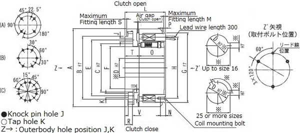
Diameter A
[mm]Diameter B f7
[mm]Diameter C H7
[mm]Diameter D max H7
[mm]Diameter D Pilot Hole H7
[mm]Diameter E
[mm]Diameter F
[mm]Diameter G f7
[mm]Diameter H
[mm]Diameter I (Coil Mounting Hole)
[mm]Diameter J (Ream Hole)
[mm]Diameter K (Bolt Hole)
[mm]Diameter U (Spot facing Hole)
[mm]EZL5 90 75 53 40 10 64 49.0 80 74 3-M4 2-ø5 4-M5 ø9 EZL10 105 85 65 45 14 75 57.0 94 82 3-M4 2-ø5 4-M5 ø9 EZL16 115 100 70 50 18 85 62.0 102 90 3-M4 2-ø6 4-M6 ø11 EZL25 125 105 75 55 20 90 68.0 112 100 3-M4 2-ø8 4-M6 ø11 EZL40 140 115 85 60 25 100 74.0 125 110 3-M6 3-ø8 6-M6 ø11 EZL63 160 130 95 70 30 115 85.0 140 125 3-M6 3-ø8 6-M8 ø15 EZL100 185 155 115 80 35 135 97.0 164 148 3-M8 3-ø10 6-M8 ø15 EZL160 215 180 130 95 40 155 113.0 190 170 3-M8 3-ø10 6-M10 ø18 EZL250 250 210 150 110 50 180 130.0 224 200 3-M10 4-ø12 8-M12 ø20 EZL400 280 235 175 125 60 205 148.0 258 235 3-M10 4-ø12 8-M12 ø20 -
Click the arrow icon in the table below to switch from ascending to descending order.
scroll
Model
Length L
[mm]Length M
[mm]Length N
[mm]Length O
[mm]Length P
[mm]Length R
[mm]Length S
[mm]Length T
[mm]Length V (Spot facing Depth)
[mm]EZL5 49.0 2.5 6.0 30.5 5.0 9.0 2.0 16.5 6.0 EZL10 54.5 2.0 7.0 34.0 4.5 10.5 2.0 19.0 6.0 EZL16 62.0 2.0 7.0 38.5 5.1 12.5 2.0 21.5 7.2 EZL25 69.0 2.0 7.0 42.0 4.1 15.5 2.5 25.0 7.2 EZL40 77.0 2.5 8.0 47.0 5.6 17.0 2.5 28.0 7.2 EZL63 92.0 3.0 12.0 57.0 8.0 19.5 3.0 33.0 9.4 EZL100 103.0 3.0 13.0 65.0 8.0 21.0 3.0 36.0 9.4 EZL160 119.0 3.0 14.5 75.0 12.0 25.5 4.0 42.0 11.8 EZL250 141.0 3.0 20.0 89.0 11.0 29.0 4.0 49.0 14.2 EZL400 168.0 4.0 20.0 111.0 10.0 32.0 4.0 55.0 14.2 -
Click the arrow icon in the table below to switch from ascending to descending order.
scroll
Model
Moment of Inertia J Armature Side
[×10-2kg・m2]Moment of Inertia J Rotor Side
[×10-2kg・m2]EZL5 0.0600 0.0775 EZL10 0.1375 0.1625 EZL16 0.2250 0.2750 EZL25 0.3500 0.4000 EZL40 0.6750 0.7000 EZL63 1.2500 1.5000 EZL100 3.0000 3.2500 EZL160 5.5000 6.2500 EZL250 11.2500 13.0000 EZL400 21.2500 21.7500 -
1.Applied hole location on outer body is either of (A) EZEL 2 - 25, (B) EZL 40 - 160 or (C) EZL250・400.
2.Please indicate dimension of the part marked. (If nothing is indicated, product with prepared hole shall be delivered).
3.Since product with prepared knock pin hole is delivered, it shall be processed at assembly.
Featured Products
Engineering Information
Technical Data
Precautions of Use
Product Topics
Industry
Contact Us
Please click the inquiry type below according to your question. Each product / sales representative will respond to you.